My final project is to create a toy bee that waves his wings to
"dance" to music.
In the spirit of spiral development, I plan to develop different
iterations to achieve the desired effect eventually.
V1.0: Microphone detects if there is sound. If there is
sound, send a signal to servo motor to trigger movement of the
wings. V 2.0: Implement better control of servo motor movements
(speed and direction) to achieve better effect of the dance. V 3.0: Implement better detection of sound by adding low pass
filter and more refined coding in translating different kind of
sound to different movements. V 4.0: Integrate the wing movement feature into the overall
project, which includes movement of other parts of the toy bee and
an embedded speaker in the bee.
This is how far I got to by Tuesday night: The bee waves his wings
if you press the button. I also implemented microphone but it has
some problem. VIDEO
Getting Started: A Failed Attempt to Integrate with
Previous Project
The wing movement feature is intended to be a feature to add on to
our prototype of BeeWhiz. So
my original wish is to add this development effort to our (one and
only) old prototype. However, the prototype stopped working a few
weeks ago and our robotic engineer is no longer able to support
BeeWhiz project.
So I first set out trying to fix our old prototype by replacing two
boards, of which our previous robotic engineer suspect the chips
were burned during user test.
After the replacement, the bee still does not function. I tried to
troubleshot other part of the prototype, but it turned out that it's
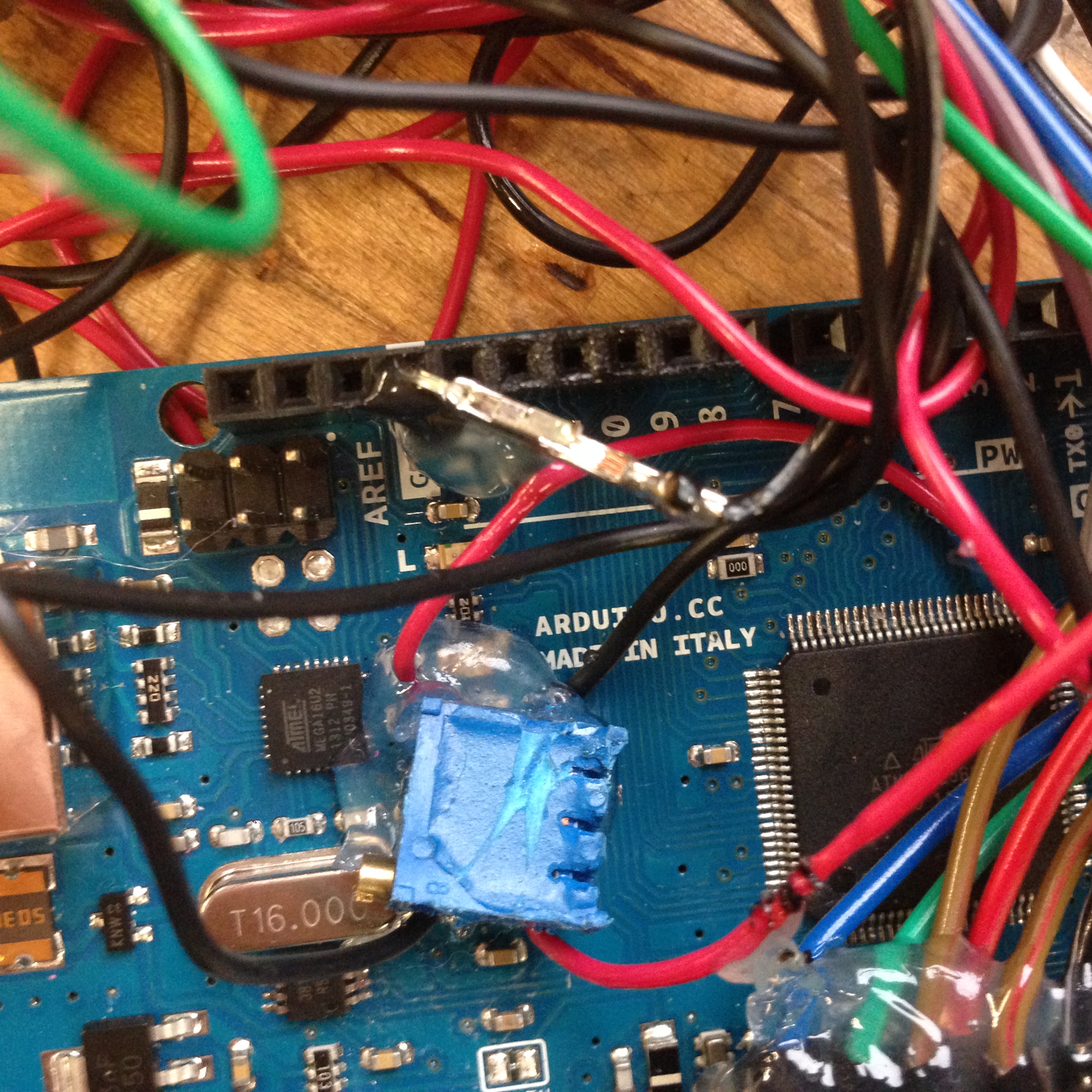
very hard since we did not have any documentation for the previous
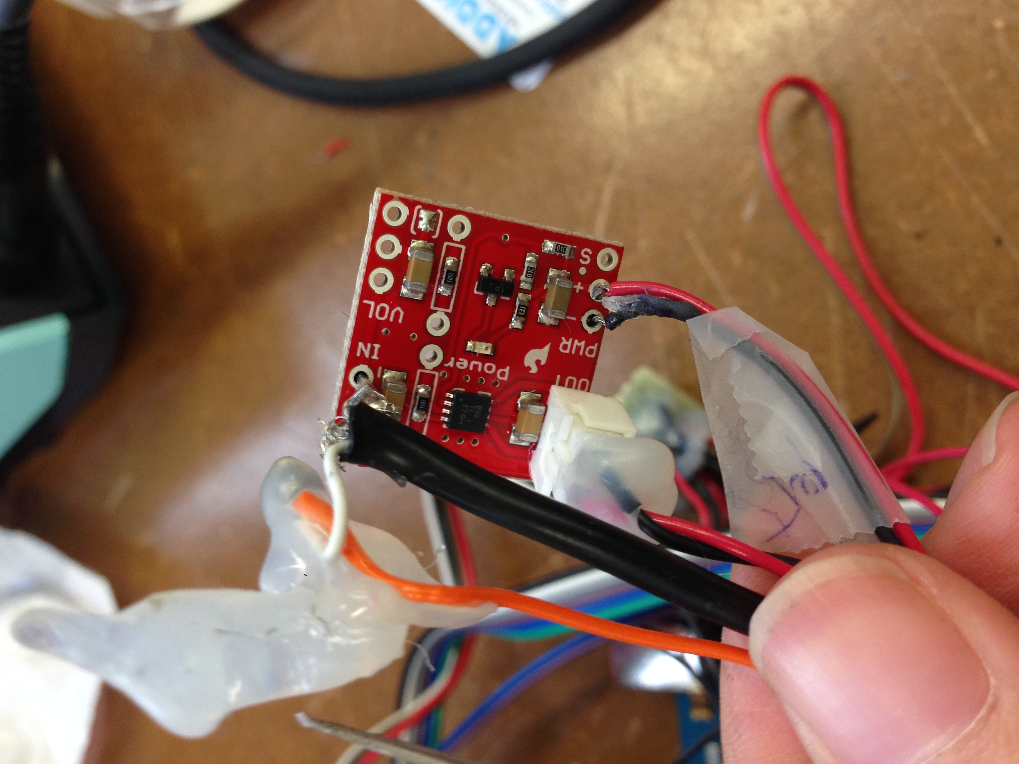
work. And our robotic engineer put hot glues around all the
connection to increase the strength of the connections. This was a
quick and dirty fix in development process, but as a result it is
almost impossible to see what's inside every glue clot without
heating it up and potentially damaging the connections.
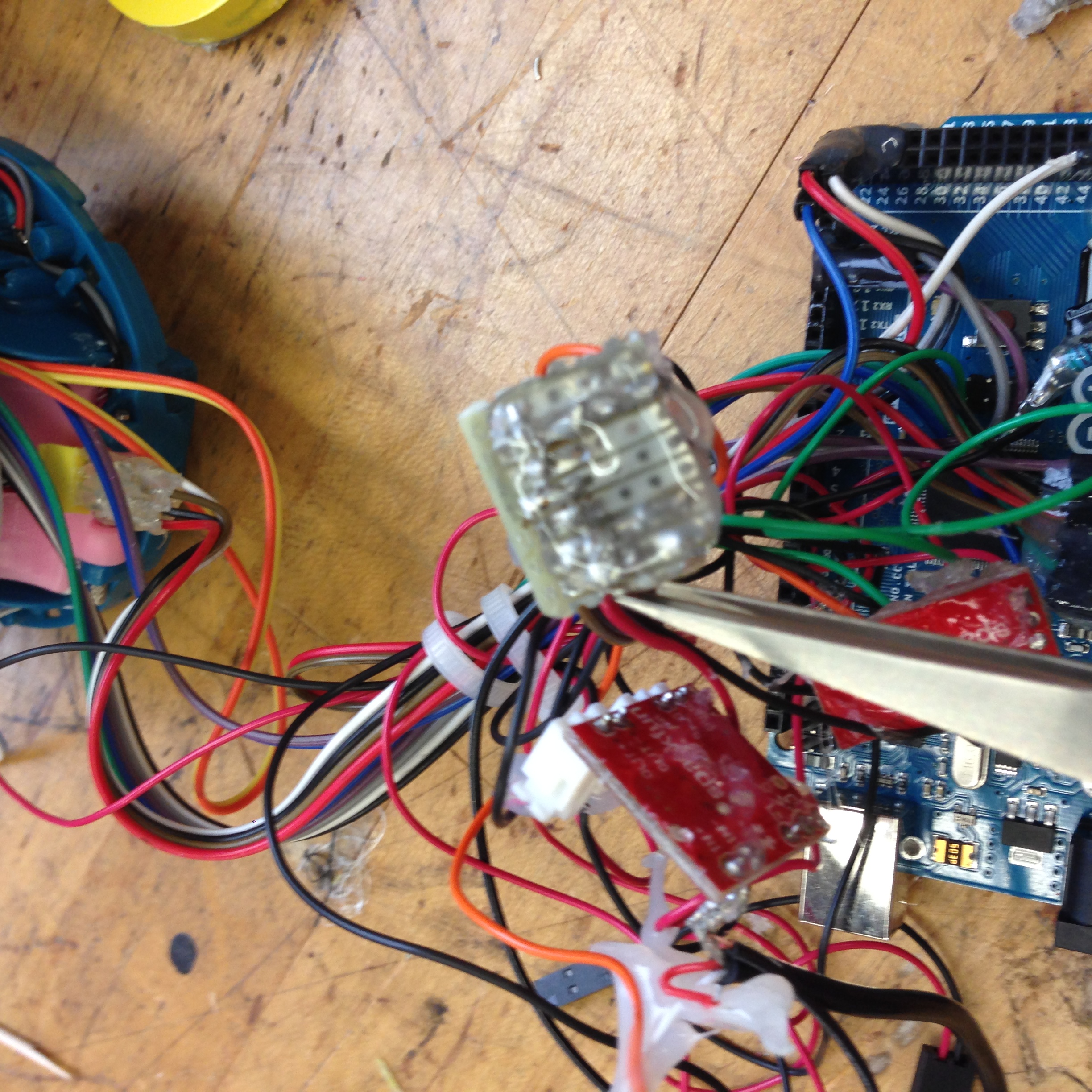
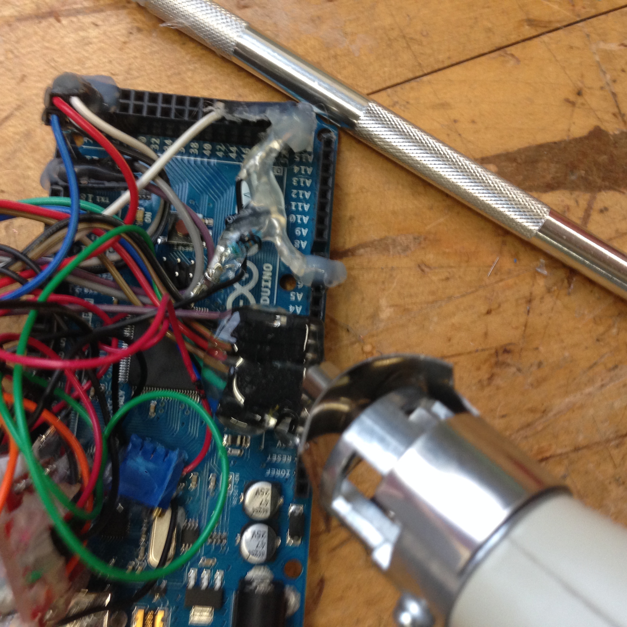
This is how it looks like inside the prototype. I took pictures to
try to figure out the connections among different parts (Arduino +
hacked furby + stuffed animal outfit).
As time is running out, I decide to park the idea of fixing the old
prototype and build the new feature into it. Instead, I decided to
develop the wing movement feature as a stand-alone project and leave
the fixing and integration after this week. @HTM, if you know of
anybody who would be interested and available in helping with
rebuild / fixing the BeeWhiz prototype, please let me know. Much
appreciated!
Restart the Project: Taking a Stand-alone Module
Development Approach
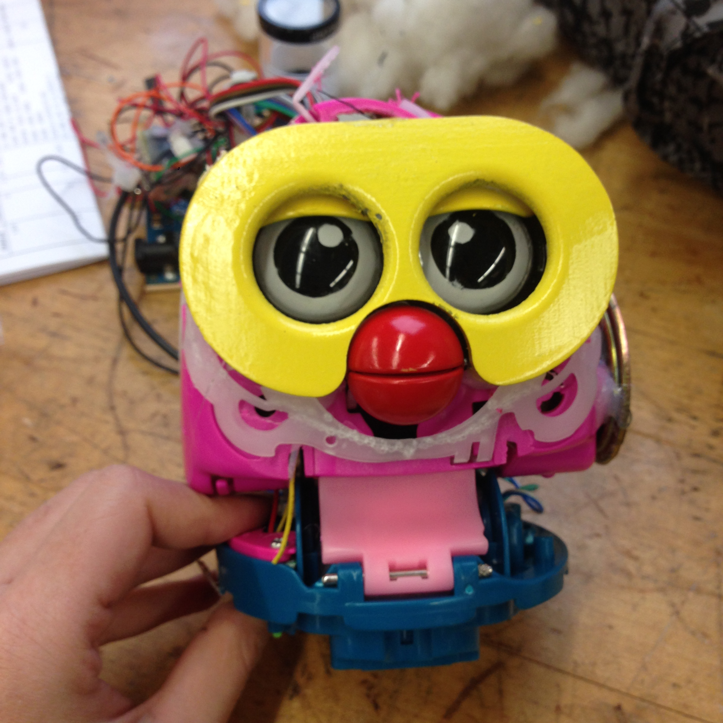
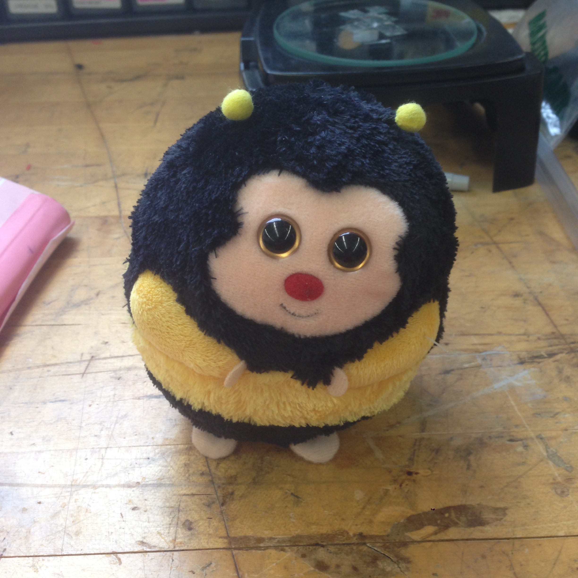
I bought this buddy from Amazon as the toy bee that I will implement
the wing movement function on.
3D Design
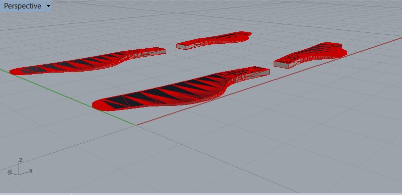
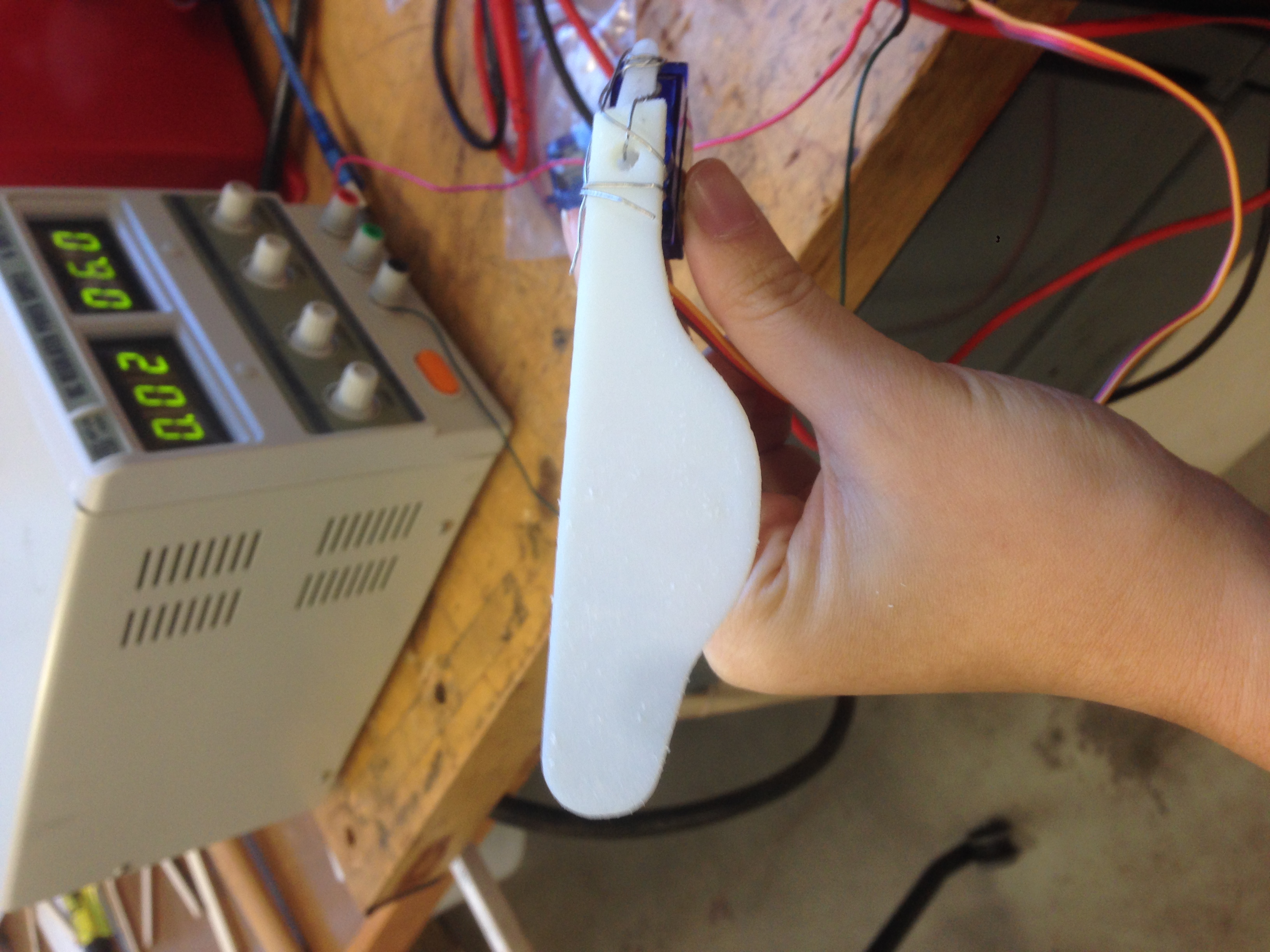
I designed the 3D models of the wings in Rhino and printed two sets
of them, one set from GSD 3D printer and another set from MakerBot
in our lab.
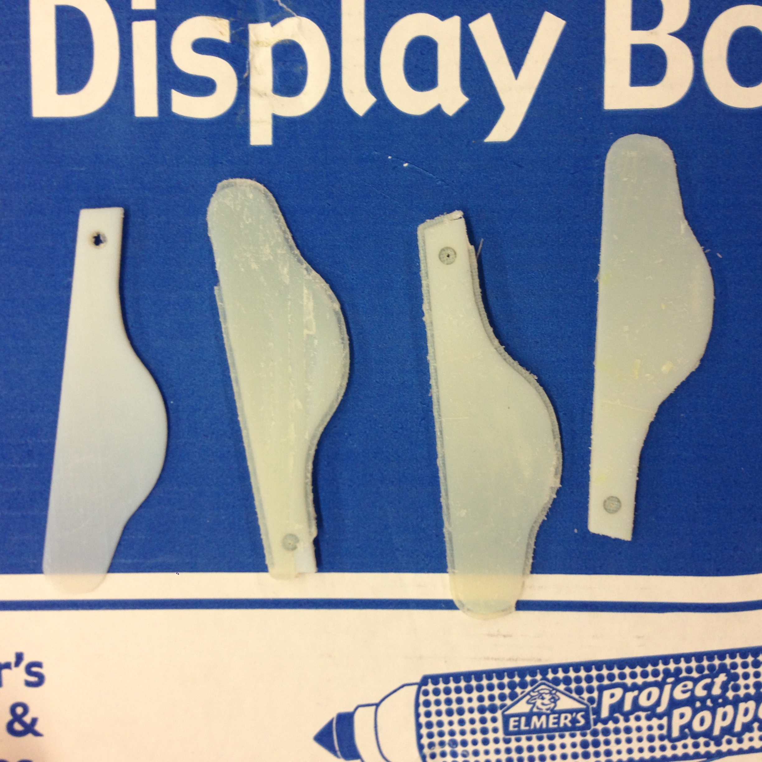
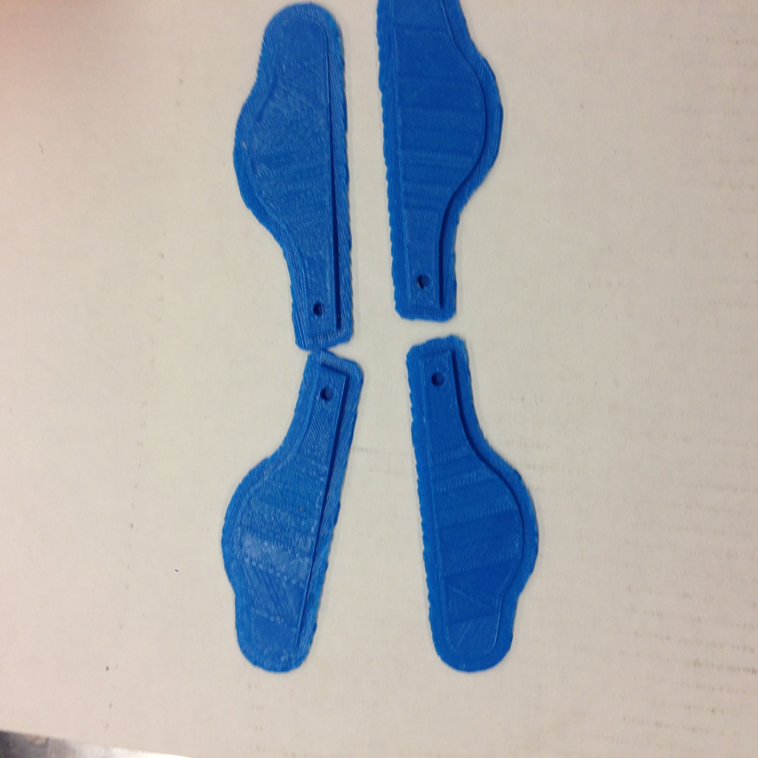
Here's the design file. And below are two
sets of wings that I printed. The blue ones are from Maker Bot and
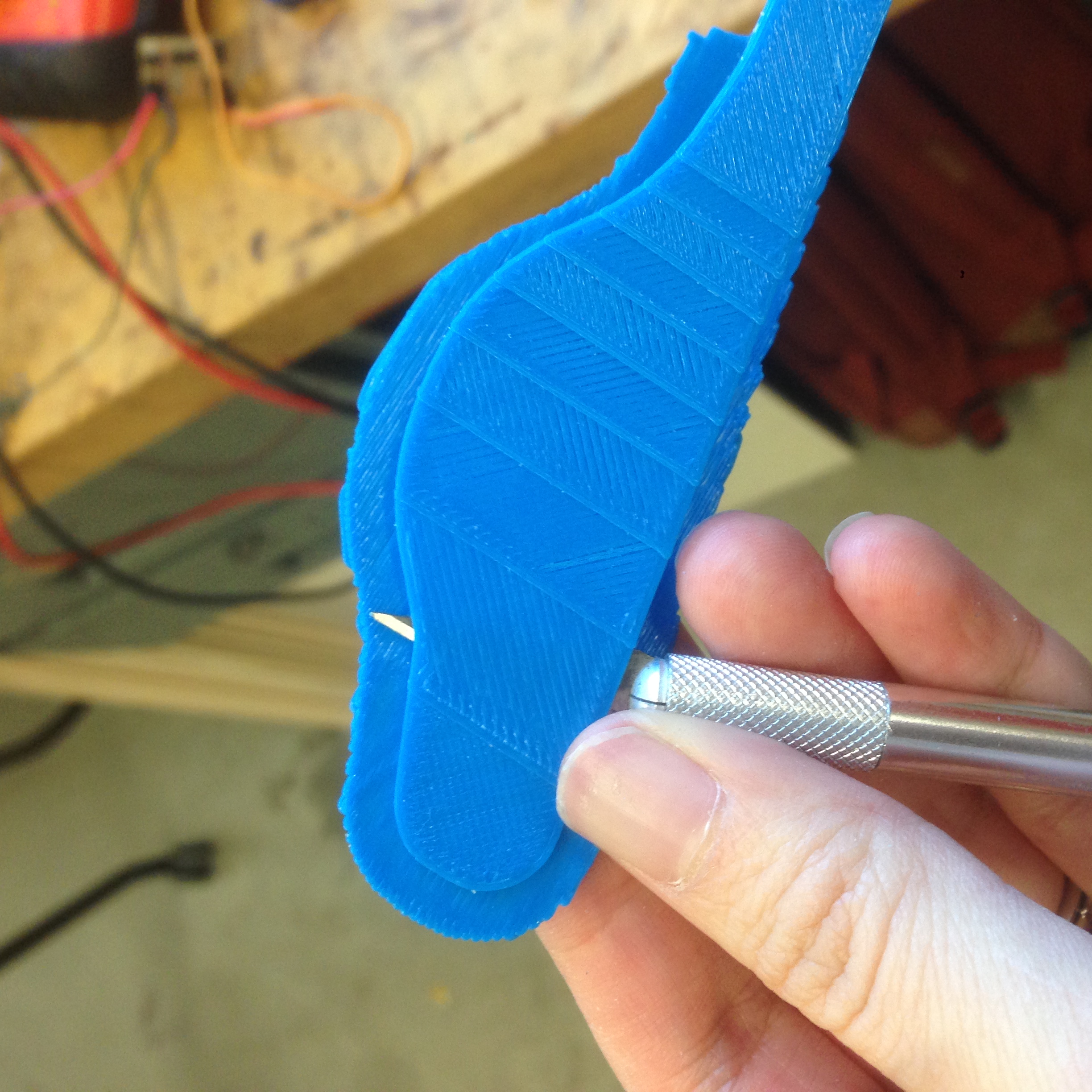
the white ones are from GSD 3D printer. And I used a knife to take
off the support structure from the blue wings.
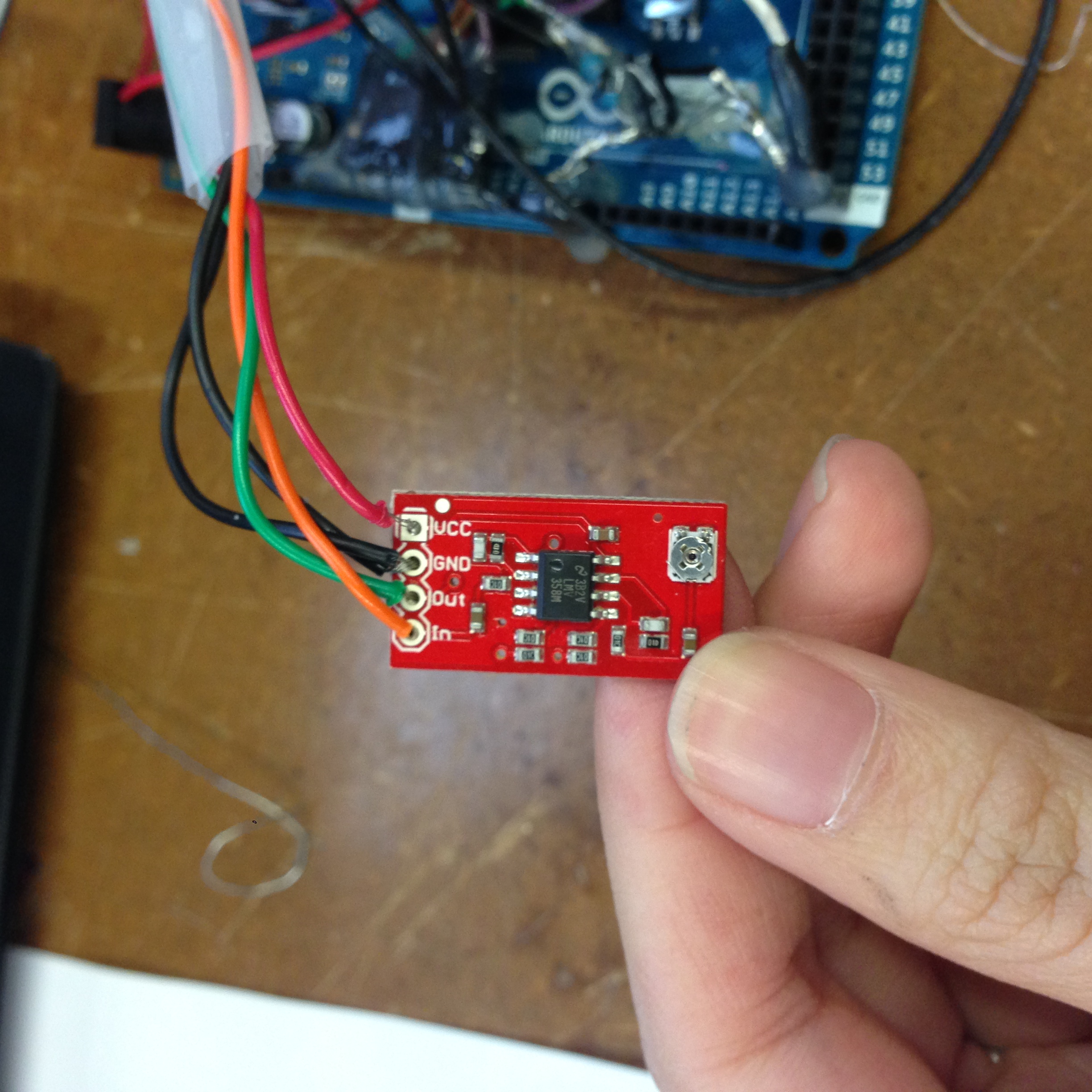
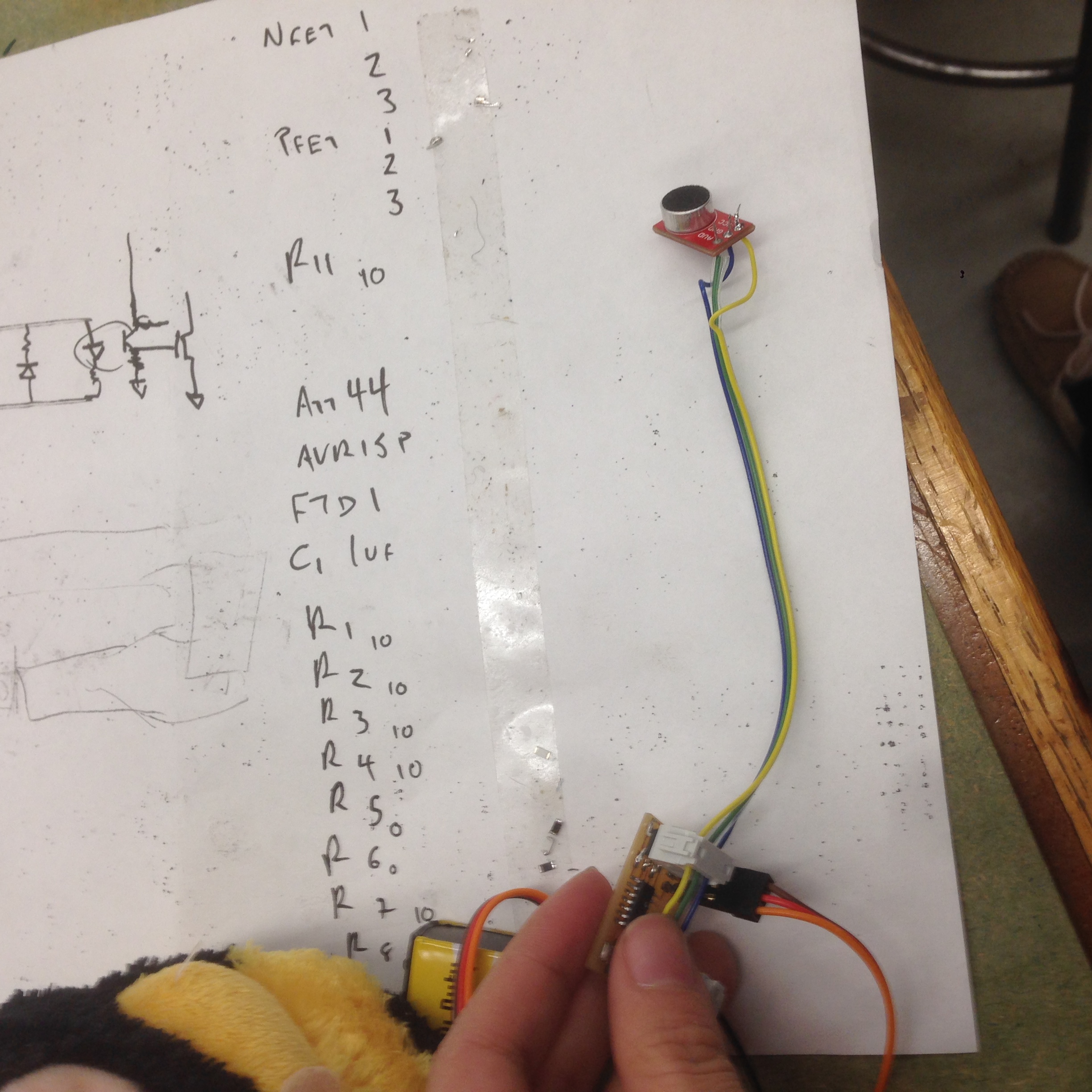
Electronics
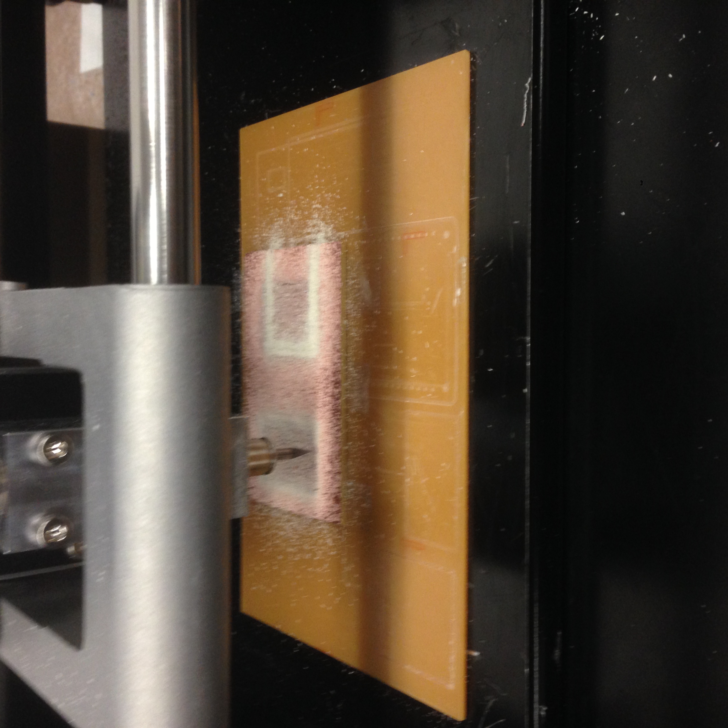
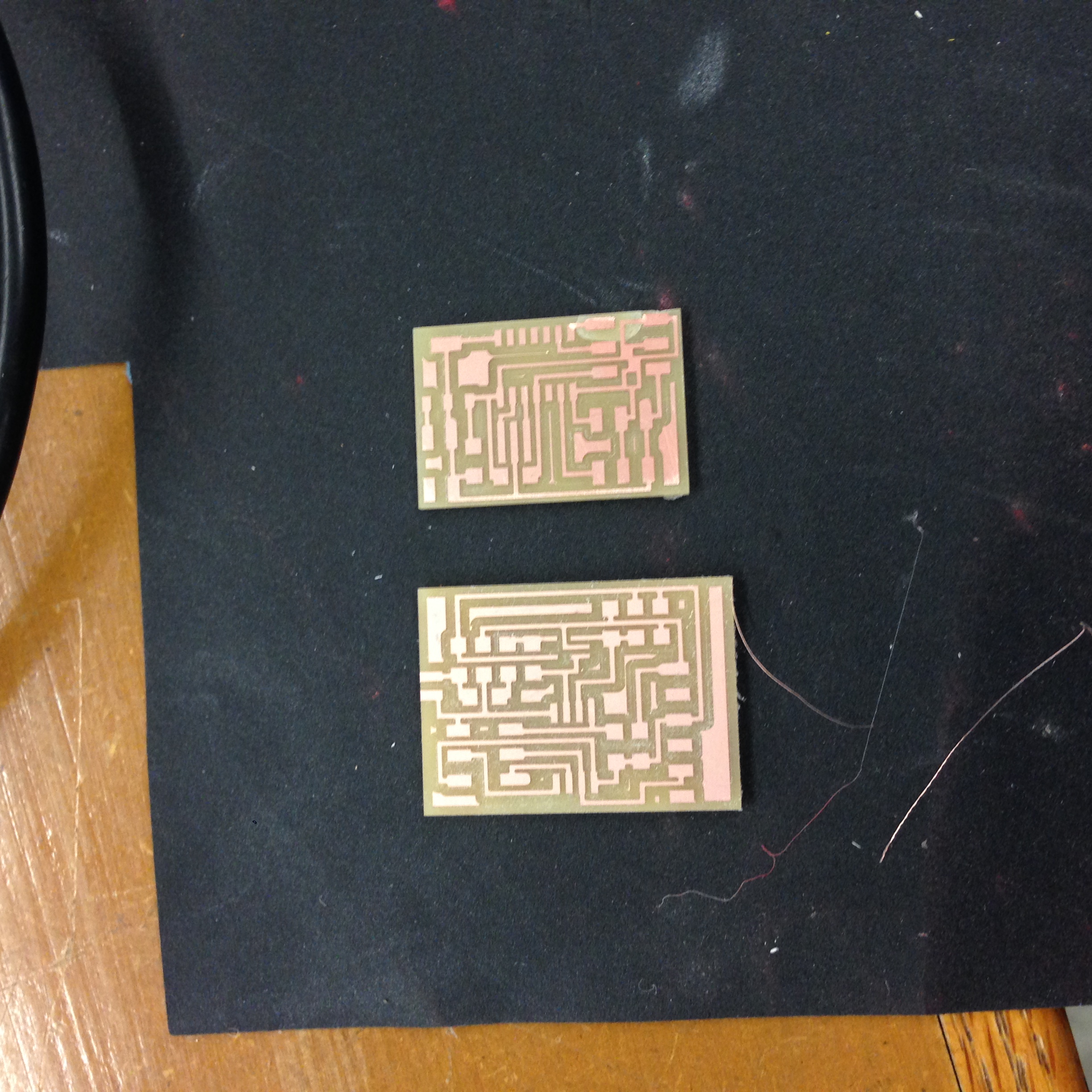
I redesigned two of Neil's boards in Eagle, the microphone input
board from Input Devices week and the servo motor board from Output
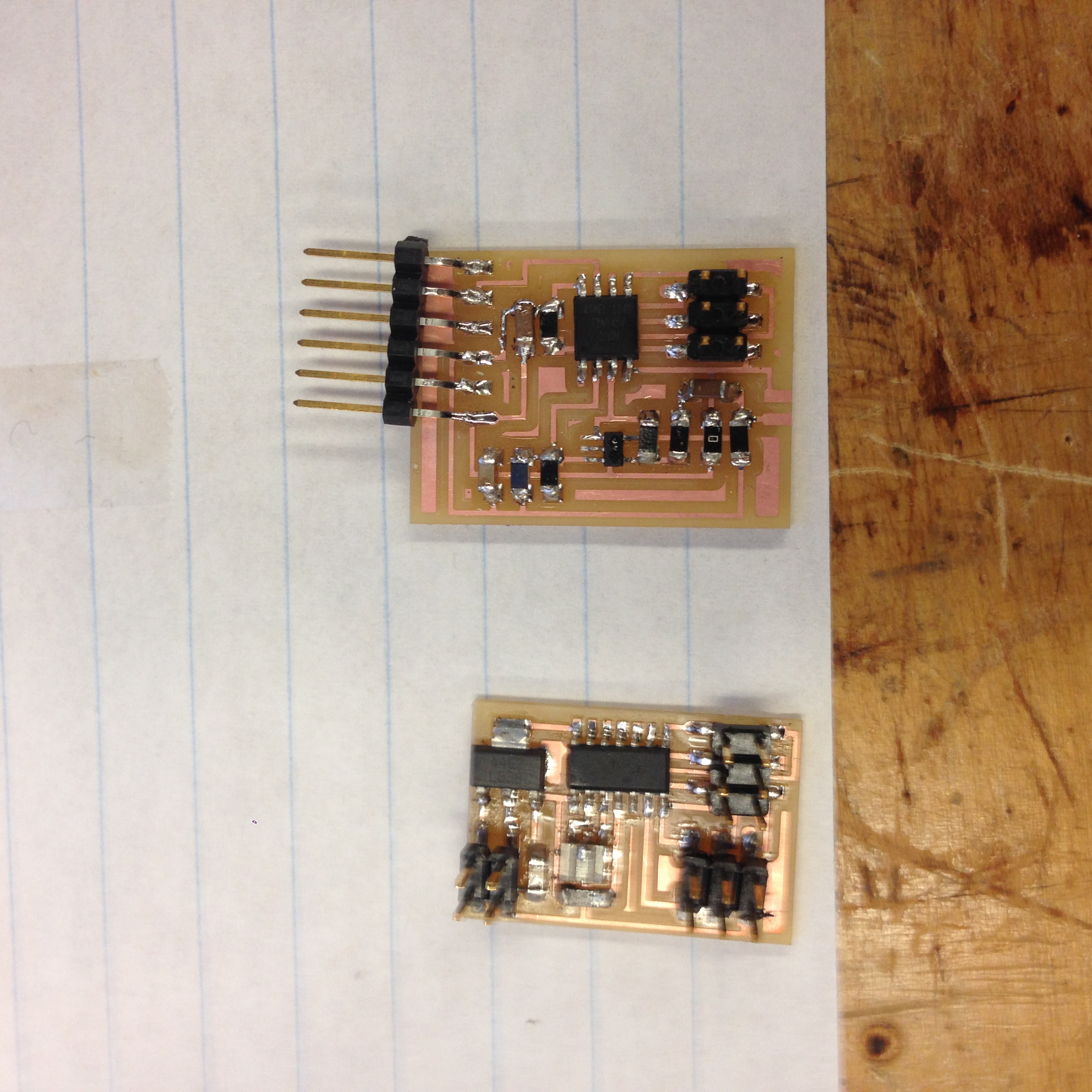
Devices week. Then I milled the boards and stuffed it.
At first, I didn't solder on the microphone since I want to make
sure that my chip is working. After I successfully programed my
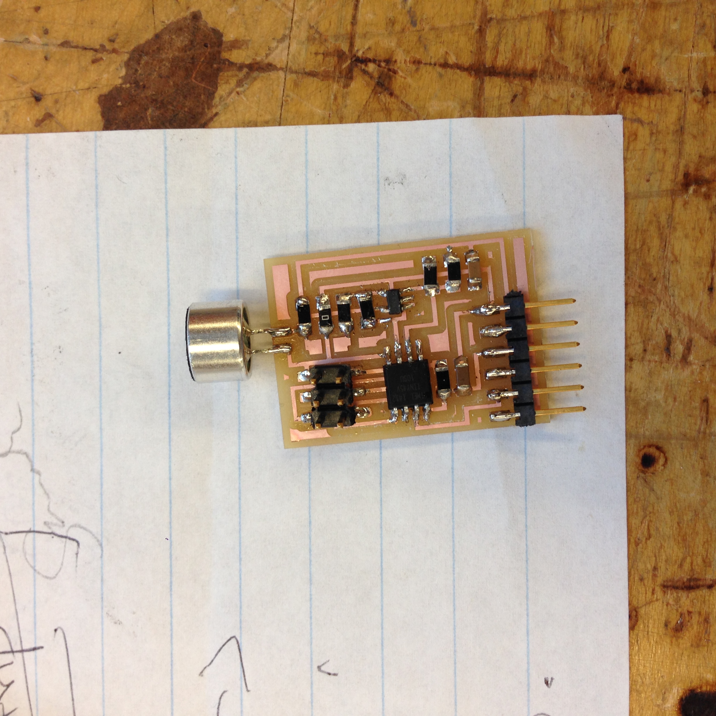
chip, I added on the microphone. For polarization of microphone, the
end with marks is negative. I also used below wire clippers as a
temporary setup to prepare to test out my code before I do a
permanent setup.
I successfully programmed both of the boards. Here are my code and make files.
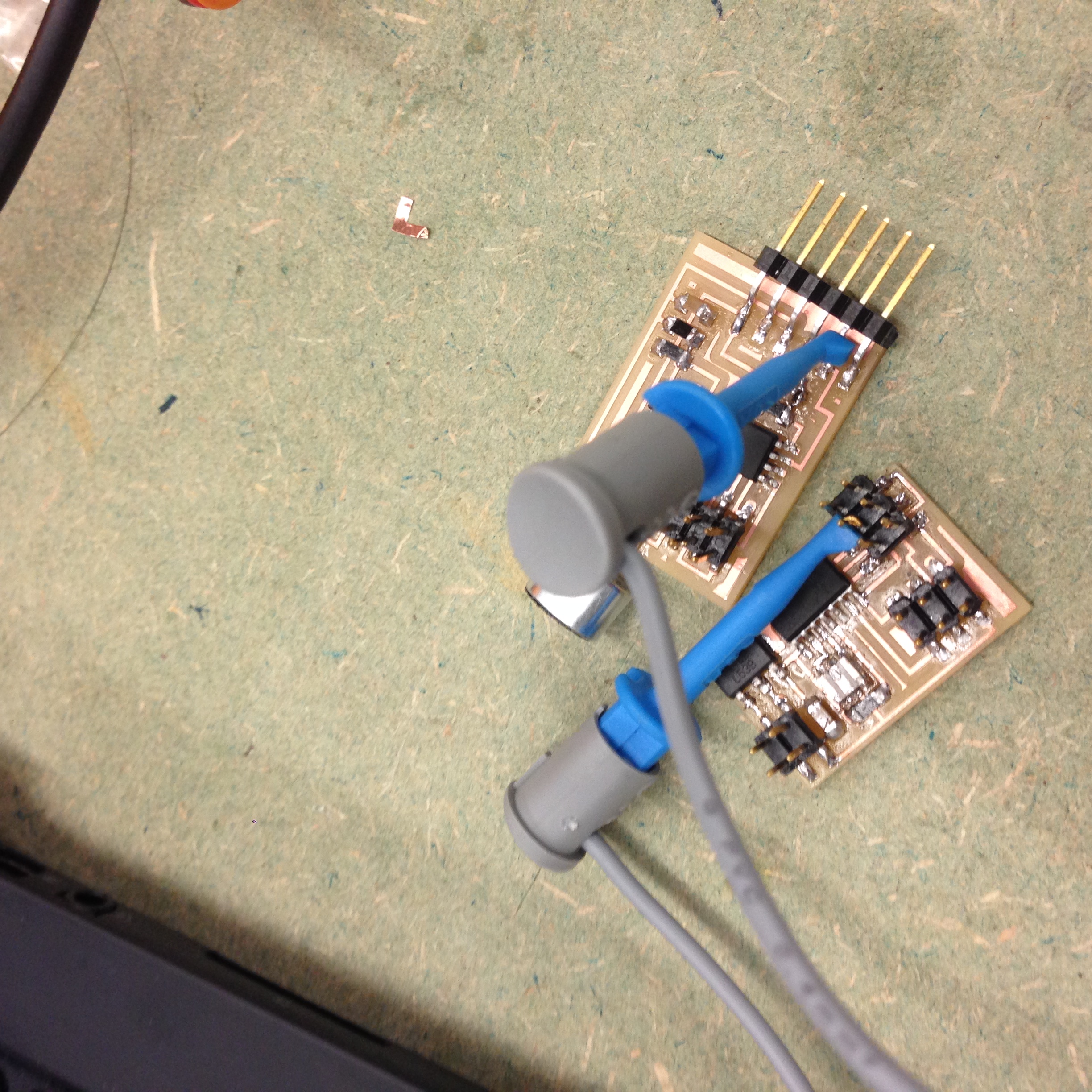
The connection between the two boards are established as follows:
If ACD>700, set PB2 of microphone board as high and a wire goes
from PB2 of microphone board to PB2 of servo motor board. On servo
motor board, if PB2 is high, trigger the servo motor movement via
PWM.
However, both boards experienced some problems when I actually power
it to see the effect.
At first, the servo motor didn't move as it's supposed to (VIDEO) because I didn't set the fuses
correctly. The board was using the internal clock instead of
external 20MHz crystal.
The fix for that is to change the make file code into: avrdude -p
t44 -P usb -c avrisp2 -U lfuse:2:0x7E:m. You can also just run this
line in command window after generating hex file.
IT WORKED!
The microphone board has a bigger problem. The board doesn't have
any serial communication when I ran python terminal. And I also
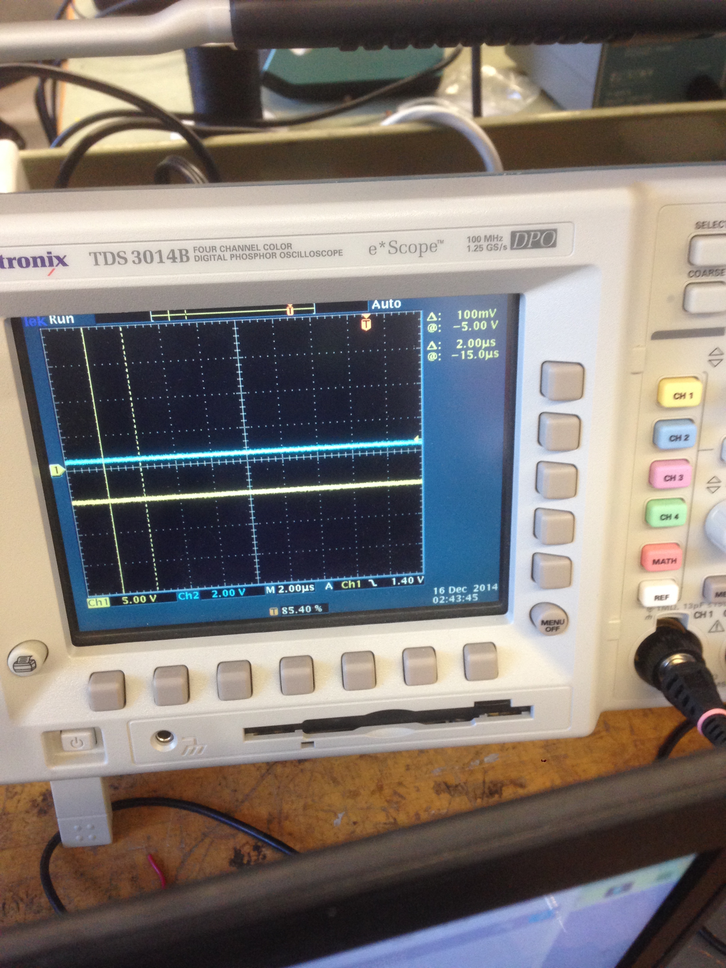
don't see any voltage changes from oscilloscope.
The voltage between ground and PB2 didn't (always) move
according to the sound. VIDEO
After checking and re-soldering the board multiple times with the
help from many great people, I still couldn't make the microphone
board work. :(
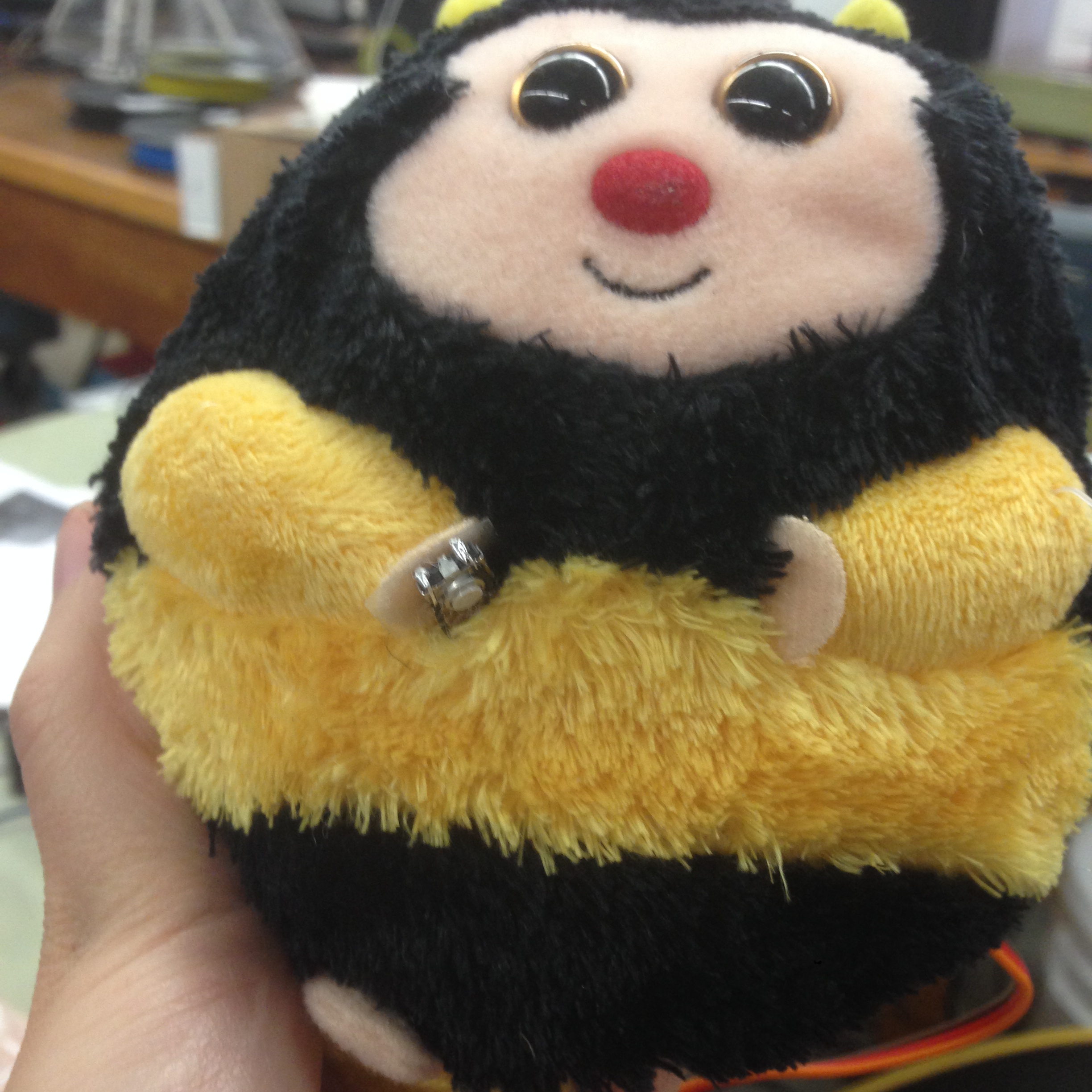
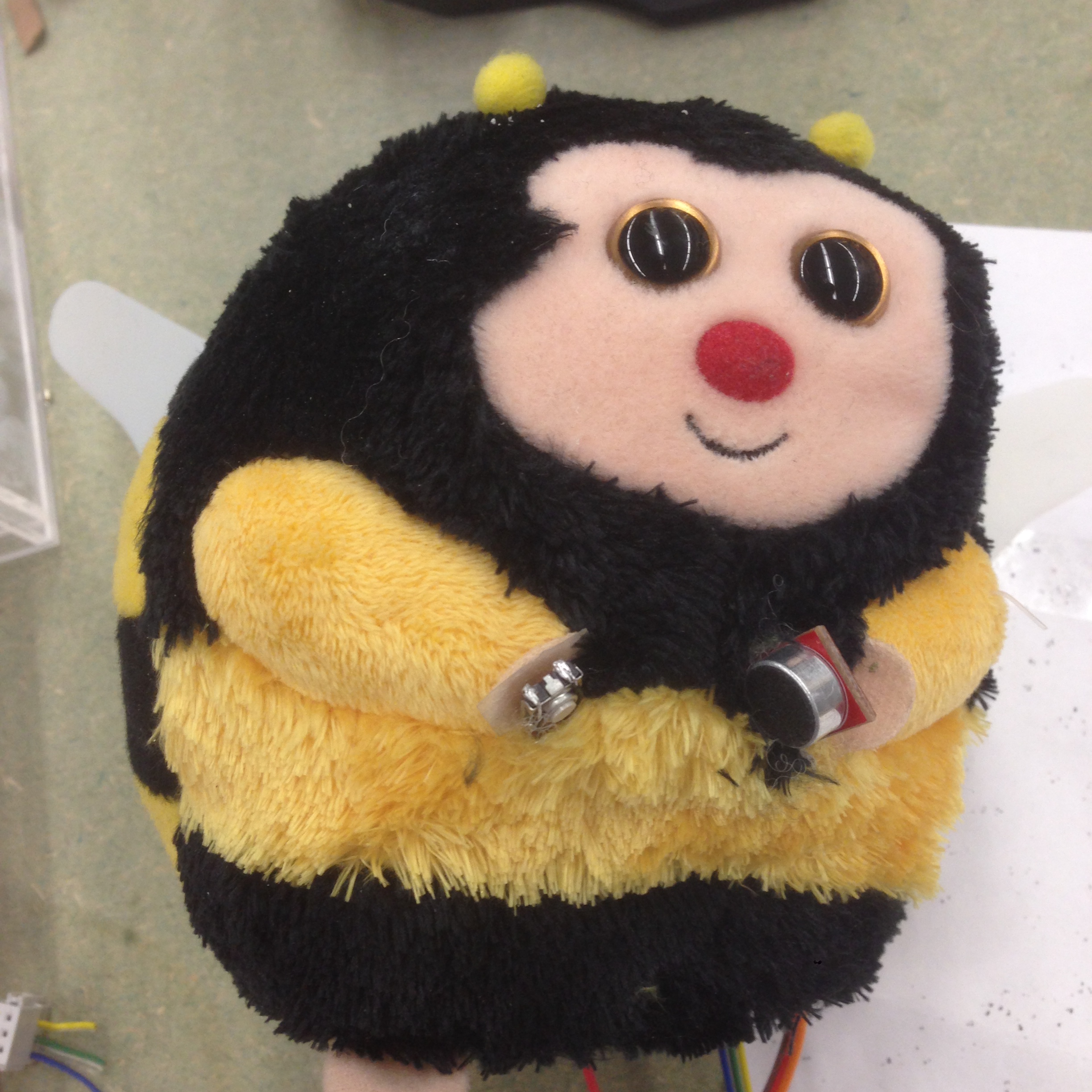
I decided to simply my project and add a button as input device.
That was easy! Shake hands with my bee and it will wave his wings
for you.
Assembly
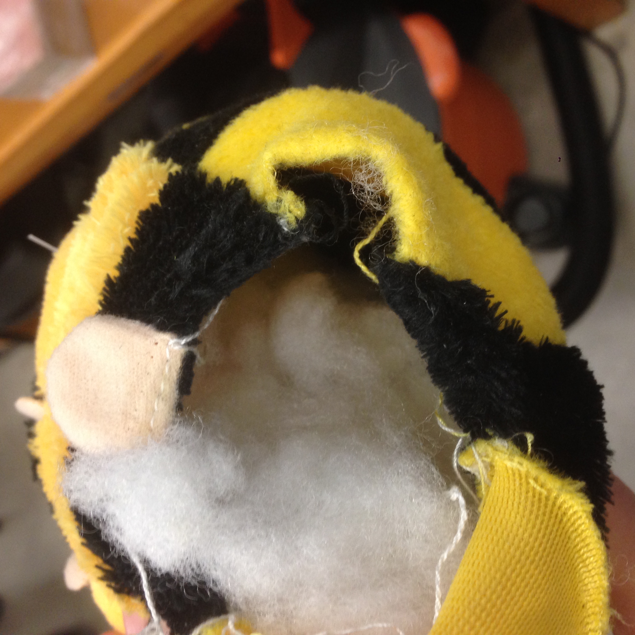
And I continued to assemble the wings, bee, the battery and other
parts.
One More Try for Microphone...
In the spirit of spiral development and ultimate resilience, I
decided to try to use a SparkFun microphone board, which has
built-in amplifier in it. I made headers for the board to connect it
with the ISP header on the servo motor board. I was hoping to use
one of the MOSI pin to take audio signal and use that signal to
trigger servo motor movement. But unfortunately, I wasn't able to
get the c code to work yet.
Learned a Lot from Final Project
During final project I've learned many things and improved many
skills, including:
Debugging board with serial monitor in Arduino and
oscilloscope...
Soldering tips including soldering a wire to the board if
traces are missing...
Use super glue to fix your board when some part of the traces
and components fell off... (Don't plug in and pull out serial
cable too often, it might tear apart your traces...)
Remove your board if it's already cut out from the PCB machine
when you clean the PCB machine with a vacuum. Otherwise the
vacuum can "eat" your board...
Use executive knife to cut out traces if the PCB machine
didn't mill it right at first...